This widget could not be displayed.
This widget could not be displayed.
Turn on suggestions
Auto-suggest helps you quickly narrow down your search results by suggesting possible matches as you type.
Showing results for
- English
- Other Products
- FAQ
- [ROG Component] ROG RYUJIN II installation/LED ins...
Options
- Subscribe to RSS Feed
- Mark as New
- Mark as Read
- Bookmark
- Subscribe
- Printer Friendly Page
- Report Inappropriate Content
Community Manager
Options
- Article History
- Subscribe to RSS Feed
- Mark as New
- Mark as Read
- Bookmark
- Subscribe
- Printer Friendly Page
- Report Inappropriate Content
on 01-29-2024 06:01 PM
[ROG Component] ROG RYUJIN II installation/LED instructions
[ROG Component]Installation of ROG RYUJIN II series AIO water cooling
[ROG Component] How to set up LCD display of ROG RYUJIN II series water cooling
Installation of ROG RYUJIN II series AIO water cooling
If you are new to the ROG RYUJIN II series AIO water cooling, you can install it on your motherboard by referring to the following steps.
(Example of RYUJIN II 360 ARGB)
Table of Contents:
- Installation of water pump on Intel models
- Installation of water pump on AMD models
- Installation of other water cooling accessories
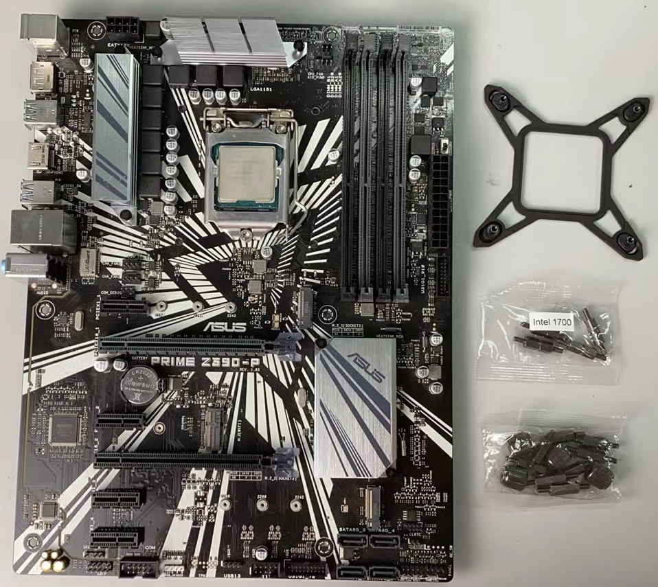
Intel models (Example:PRIME Z390-P)
* The water pump is already installed with Intel bracket by default, no need to install Intel bracket any more.
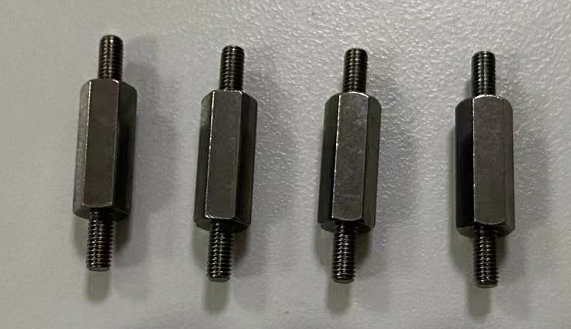
1.1 Find the backplane bracket and screw package for the MB you purchased corresponding to the Intel socket (LGA1700, or LGA115x/1200), as shown in the following figure.
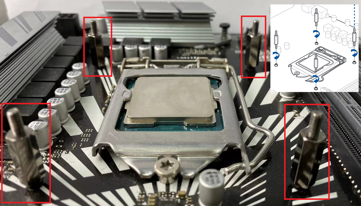
1.2 Insert the four legs of the Intel bracket from the back of the MB into the four holes near the CPU socket, as shown in the following figure.
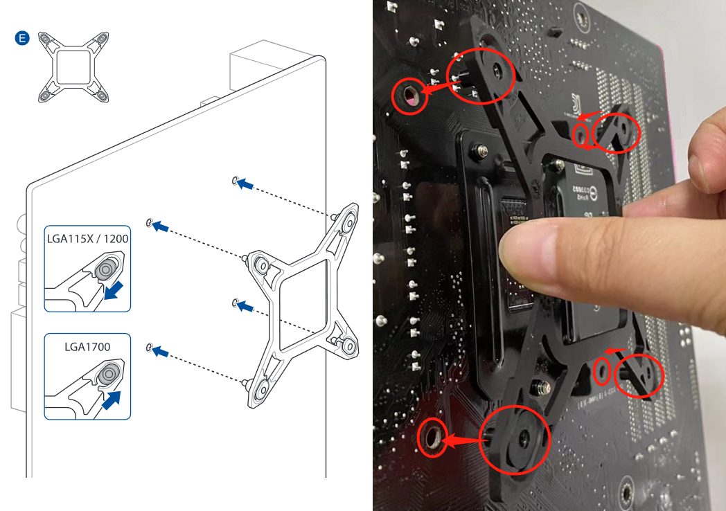
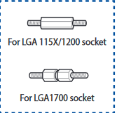
1.3 Find the long screws corresponding to the MB and respectively screw them from the front of the MB to the Intel bracket installed in the previous step, as shown in the following figure.
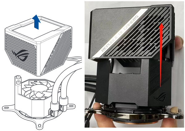
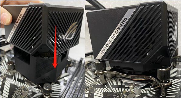
1.4 Pull up and remove the water pump's magnetic LCD screen casing, as shown in the following figure.
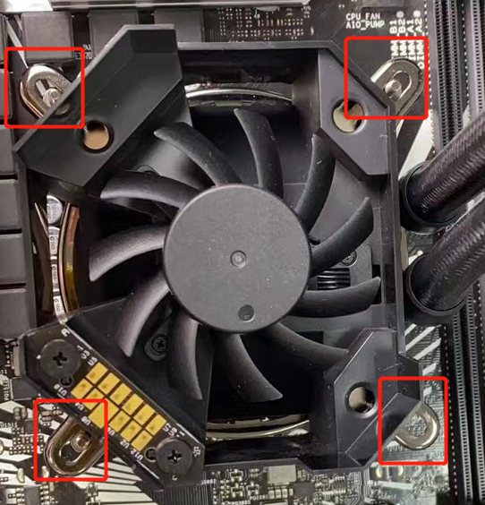
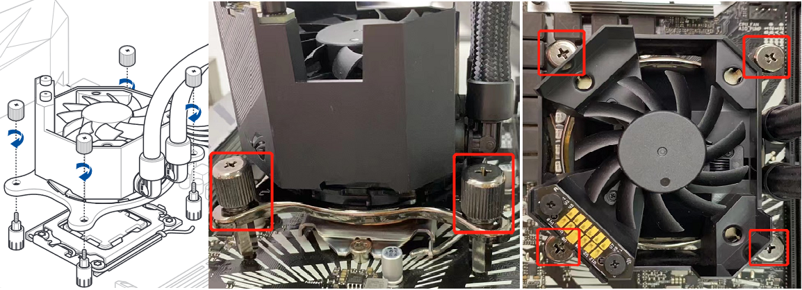
1.5 Attach the water cooling pump to the four studs in step 1.3, as shown in the following figure.
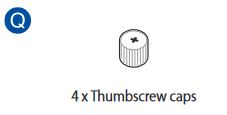
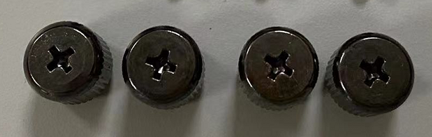
1.6 Find the screw caps in the screw package, install it on the 4 studs of the water pump and screw them tightly to fix the pump, as shown in the following figure.
1.7 Install the water-cooled pump magnetic LCD screen case removed in step 1.4 vertically, as shown in the following figure.
AMD models (Example:TUF GAMING X570-PLUS WIFI)
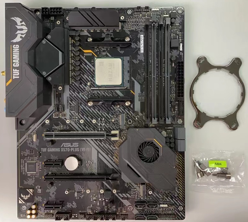
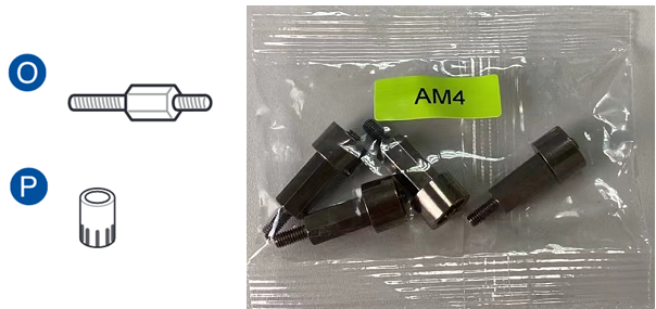
2.1 Find the MB corresponding AMD AM4 socket bracket and studs, as shown in the following figure.
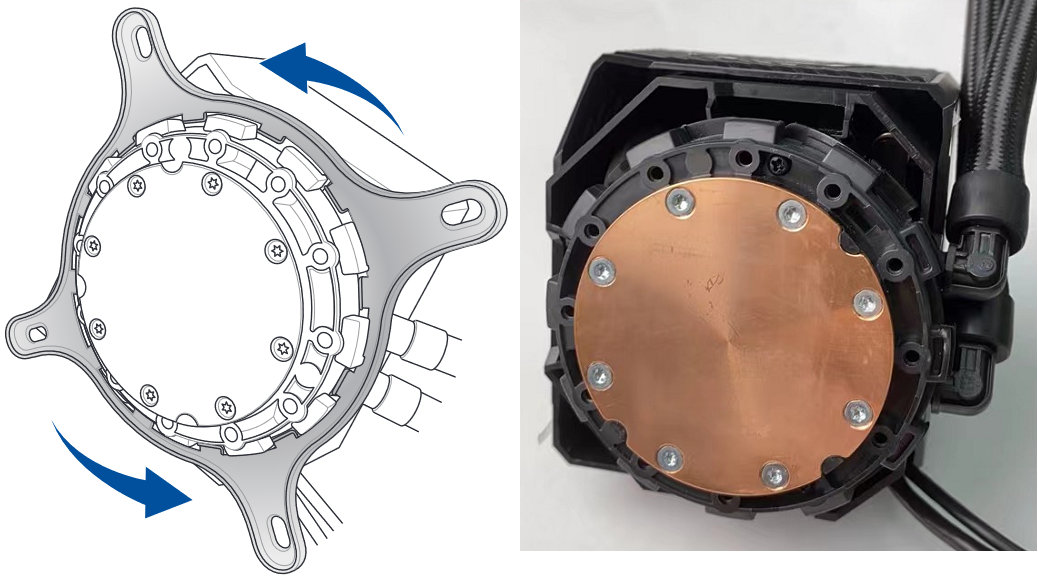
2.2 Press the Intel bracket pre-installed on the water pump and rotate it counterclockwise to remove, as shown in the following figure.
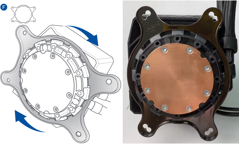
2.3 Install the AM4 bracket (press the AM4 bracket and rotate clockwise), as shown in the following figure.
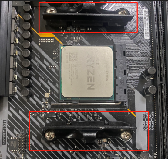
2.4 Remove the pre-installed cooler bracket from the MB, as shown in the following figure.
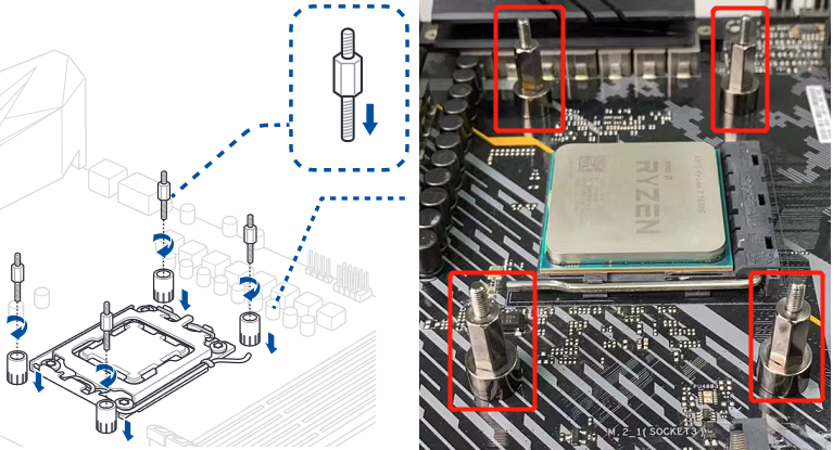
2.5 Find the corresponding studs of the AM4 socket and install them, as shown in the following figure.
2.6 Pull up the water pump magnetic LCD screen casing and remove it, as shown in the following figure.

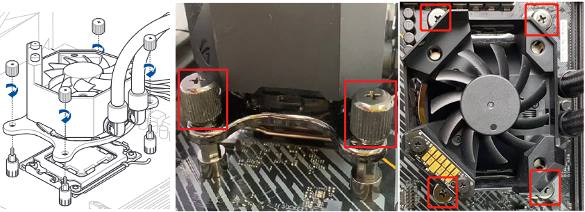
2.7 Install the water pump to the stud of the AM4 socket and screw them, as shown in the following figure.
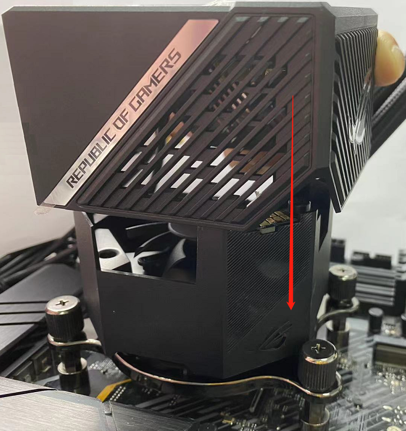
2.8 Install the water-cooled pump magnetic LCD screen case removed in step 2.6 vertically, as shown in the following figure.
Installation of other water cooling accessories
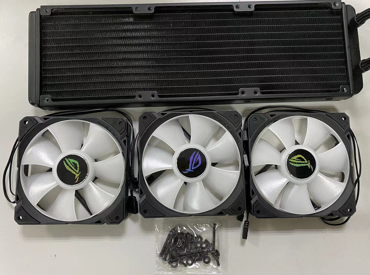
3.1 Find the three fans and the black screw package, as shown in the following figure.
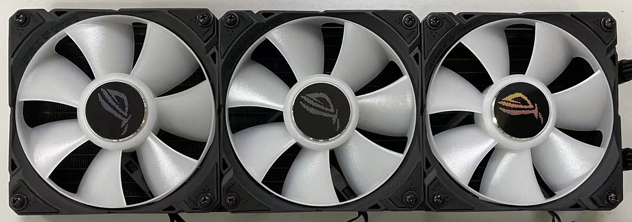
3.2 Place the three fans with the ROG logo facing outward and align them with the screw holes on the heatsink, as shown in the following figure.
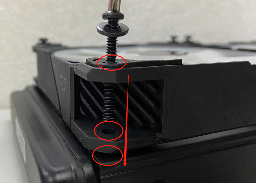
3.3 Put the washers in the screw packs onto the long screws, and thread through the three fan screw holes and lock all 3 fans to the heatsink, as shown in the following figure.
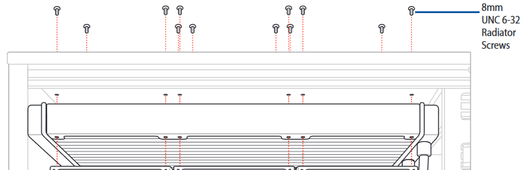
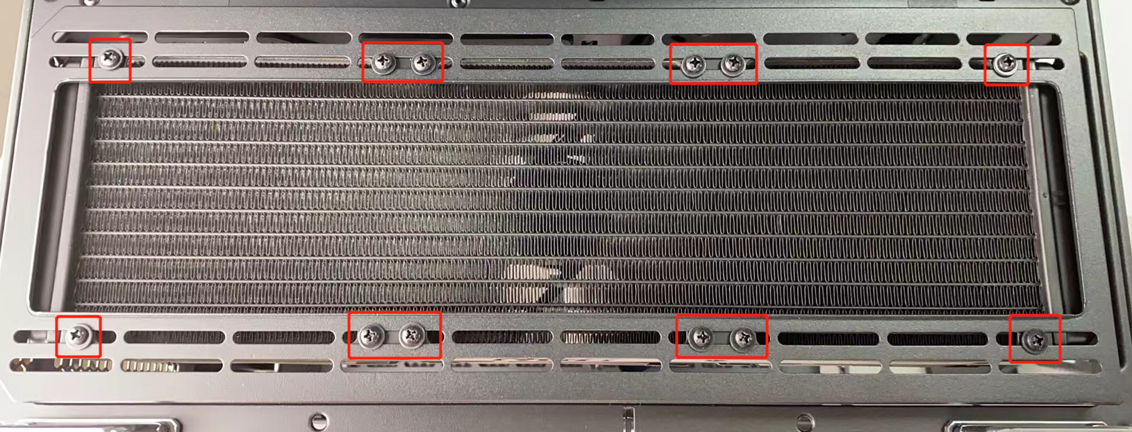
3.4 Put the washers in the screw pack into the short screws and screw the water cooling module to the chassis from the outside of the chassis, as shown in the following figure.
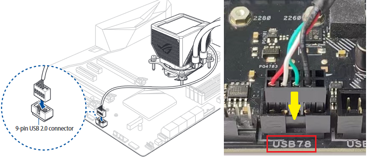
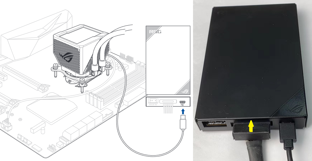
3.5 Connect the 9pin USB connector of the water cooling pump to the 9pin USB interface of the MB, as shown in the following figure.
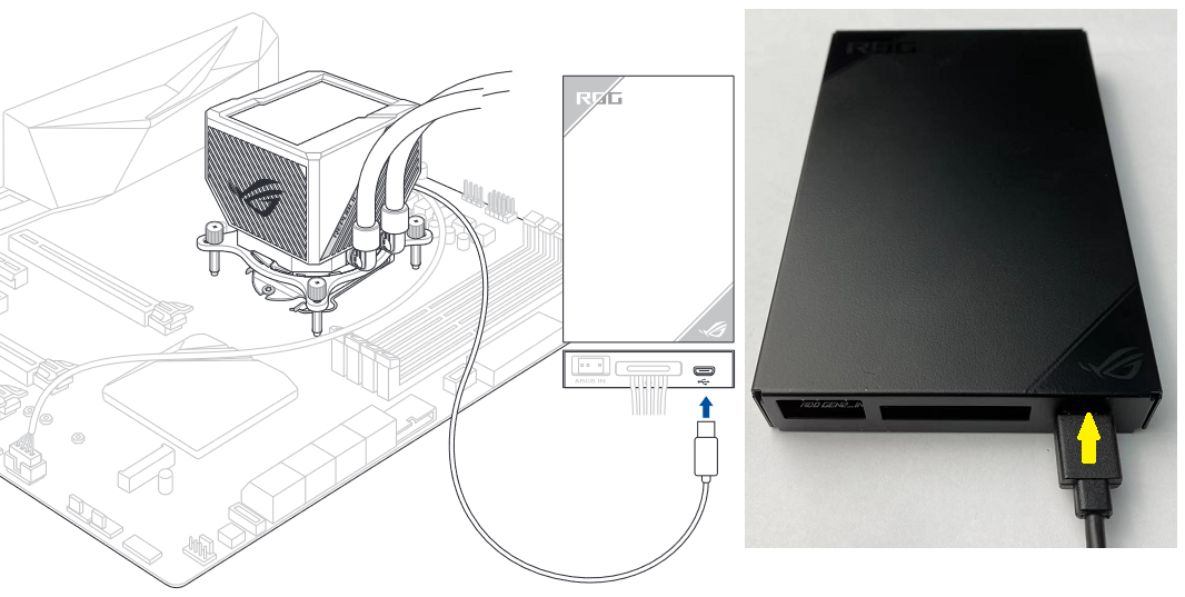
3.6 Connect the micro USB connector of the water cooling pump to the micro USB interface of the fan controller, as shown in the following figure.
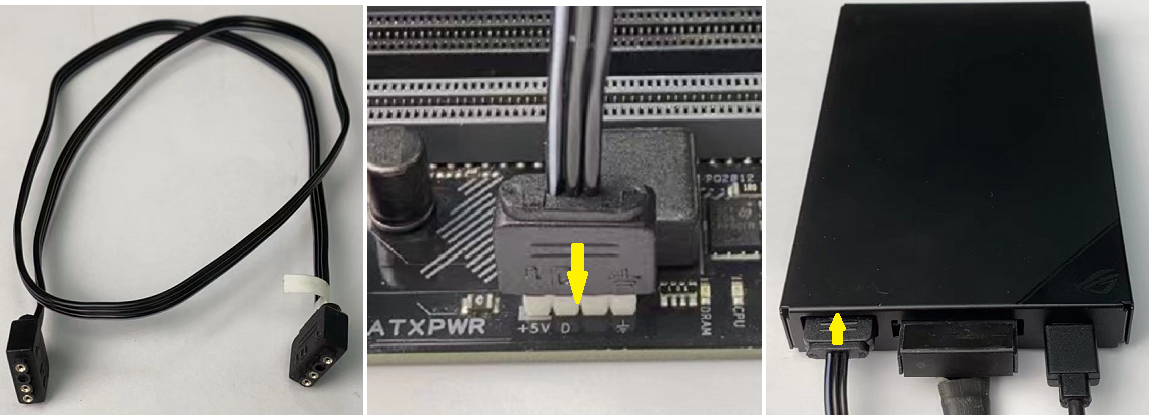
3.7 Connect the SATA power cable on the power supply to the SATA power interface of the fan controller, as shown in the following figure.
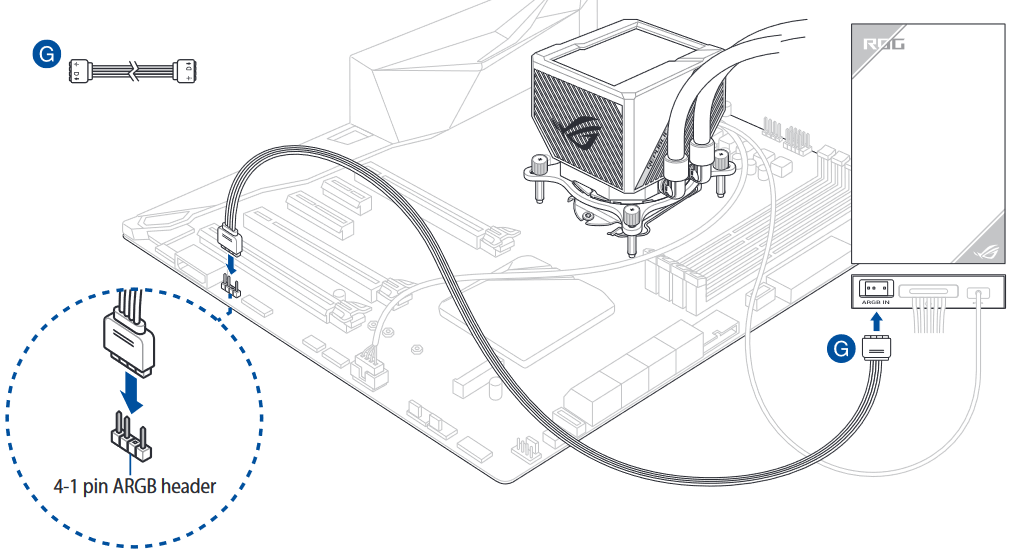
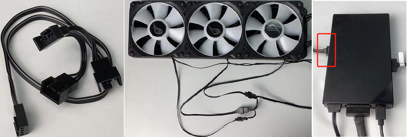
3.8 Connect one end of the 4-1 pin ARGB cable in the package to the ARGB interface of the fan controller, and the other end to the ARGB interface of the MB, as shown in the following figure.
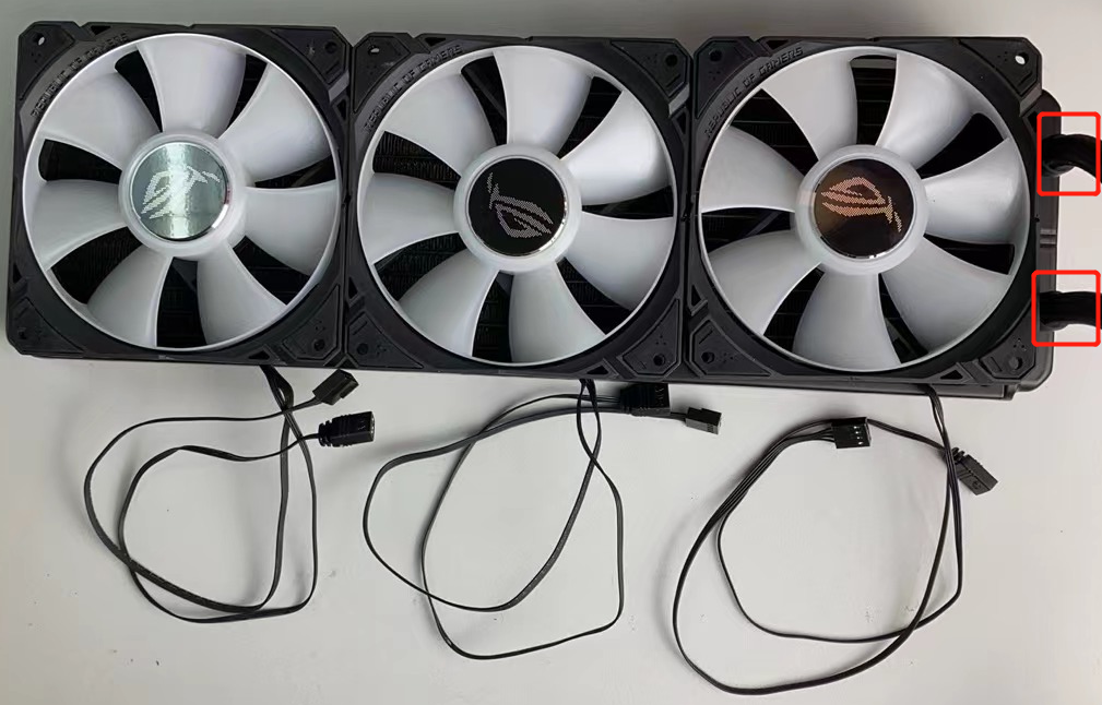
3.9 Connect the ARGB connectors of the three fans to the 4-1 pin ARGB cable in the package, and then connect the other end of the cable to one of the ARGB connectors on the side of the fan controller, as shown in the following figure.
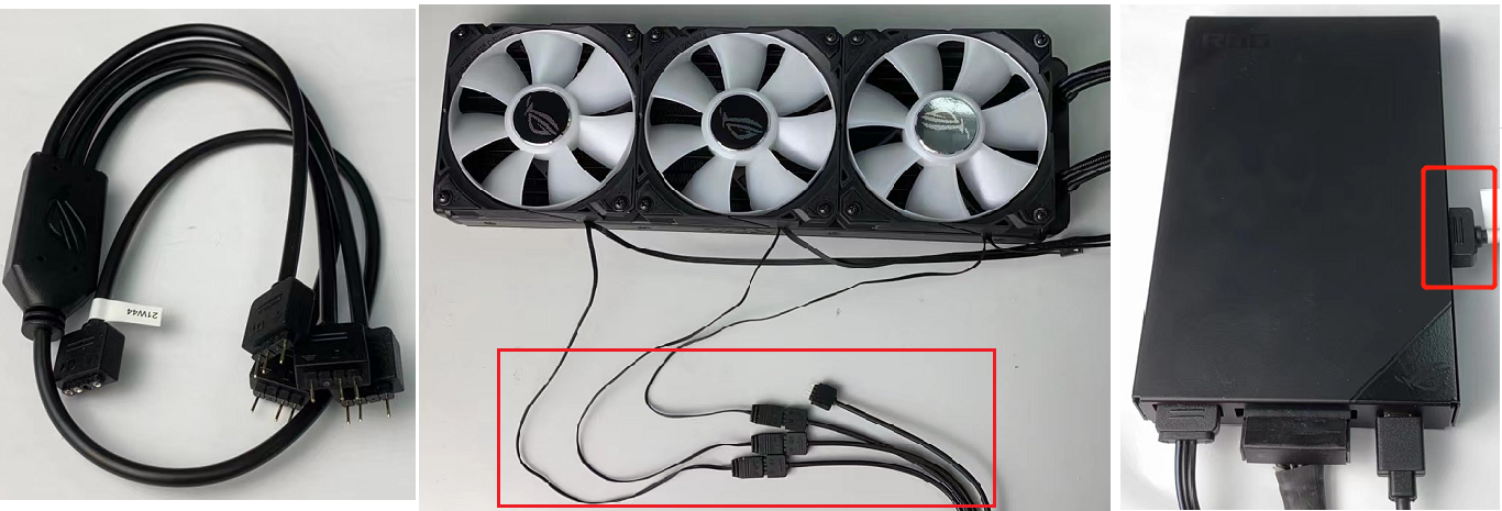
3.10 Connect the Fan connectors of the three fans to the 4-in-1 fan cable in the package, and then connect the other end of the cable to one of the Fan connectors on the side of the fan controller, as shown in the following figure.
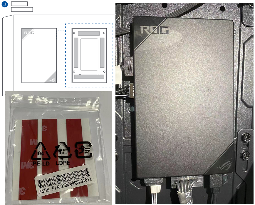
3.11 Find the tape in the package and stick it to the back of the fan controller, then stick the fan controller to the appropriate location inside the chassis, as shown in the following figure.
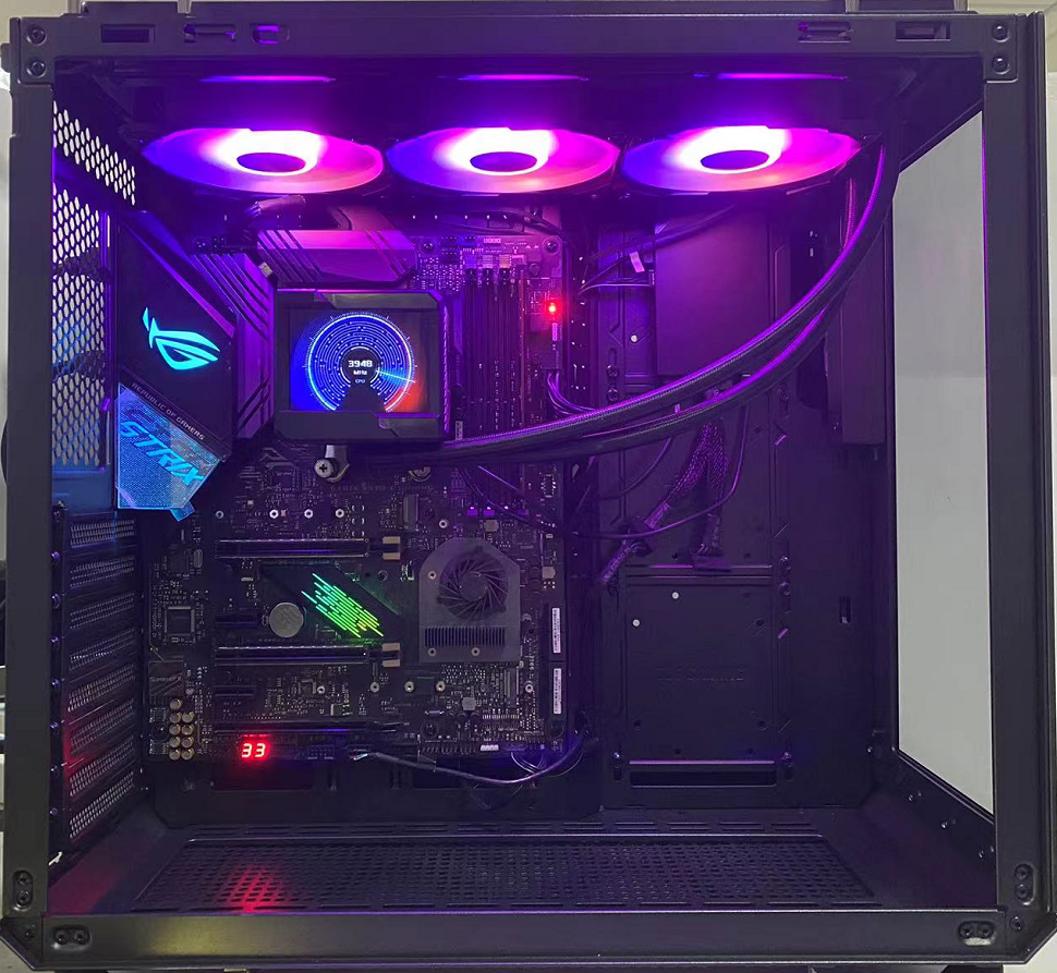
3.12 After the water cooling installation is completed, as shown in the picture below.
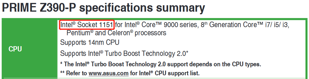
Q1: How to confirm your CPU socket of Intel MB is 115X, 1200 or 1700?
A1: As shown in the following figure, you can find your MB CPU socket in the [CPU] field of the user manual specification list.
Q2: Chassis suggestions for ROG RYUJIN II series AIO water cooling.
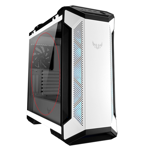
A2: Since the water cooling pump has a LCD screen, you can choose a side transparent case to see the pictures or information displayed on the LCD screen.
For example: TUF Gaming GT501 White Edition, you can see the water cooling LCD screen inside the case through the tempered glass.
[ROG Component] How to set up LCD display of ROG RYUJIN II series water cooling
If you need to set the LCD display of ROG RYUJIN II series water cooling, you can choose either of the following two methods:
The following example:ROG RYUJIN II 360 ARGB
Catalog:
Method one:Set the LCD display by ARMOURY CRATE
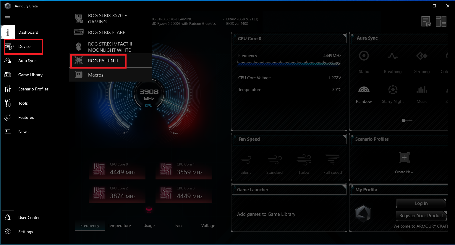
1. Open ARMOURY CRATE and click the [ROG RYUJIN II] in the [Device] column,as shown in the figure below:
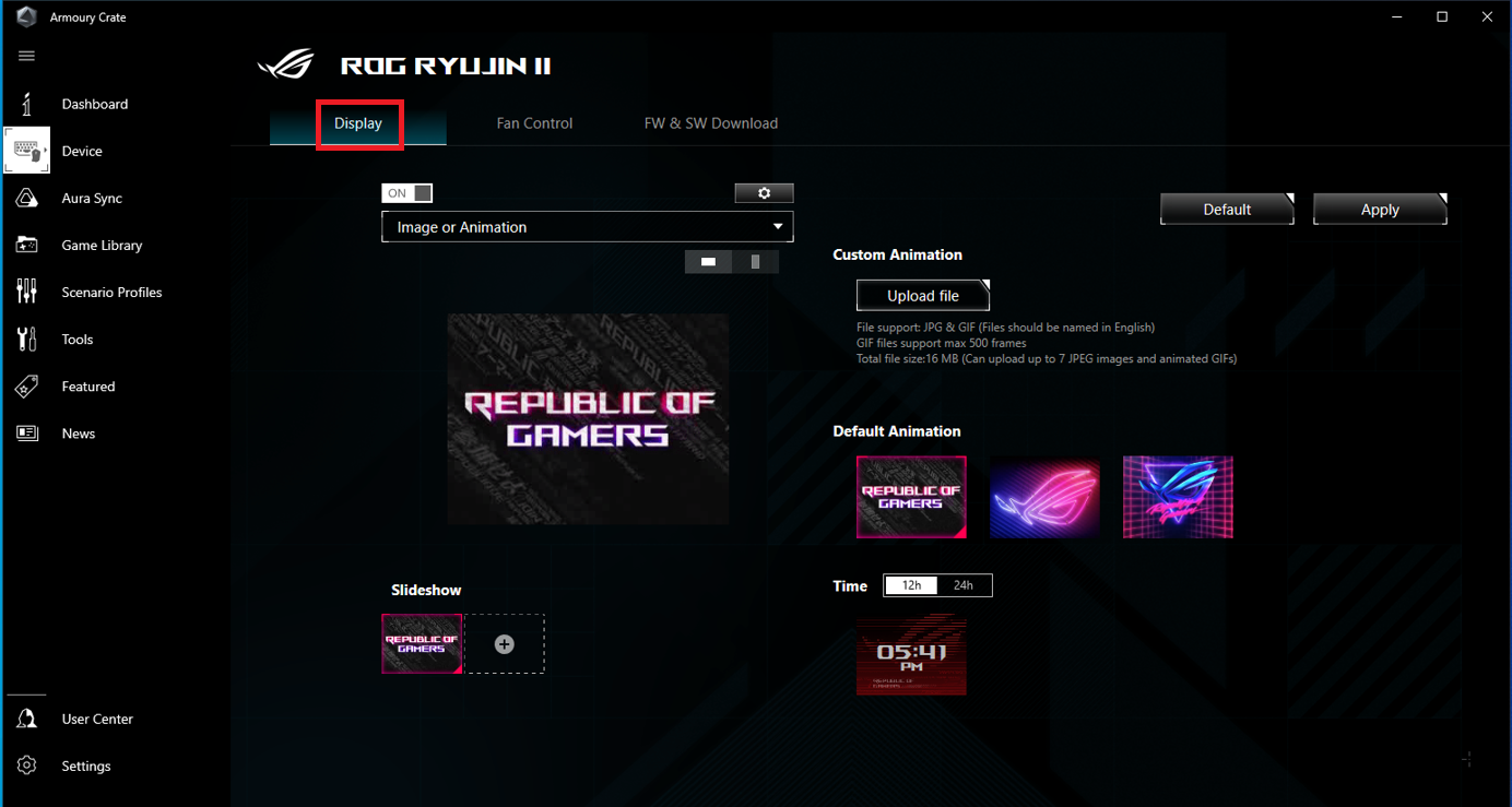
2. Click the [Display] , as shown in the figure below:
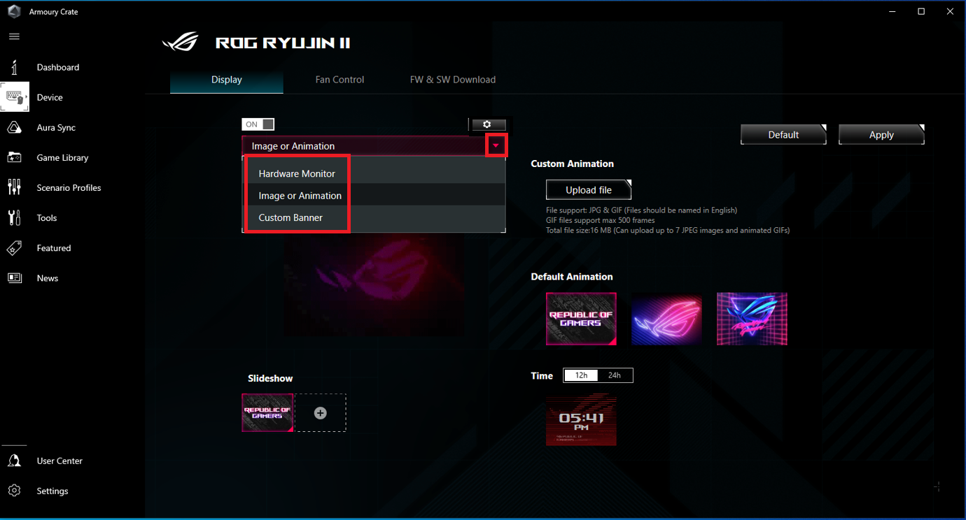
3. On the display page, you can set the LCD display content you need, click the drop-down box. As shown in the figure below, there are three display modes:
Mode one:Image or Animation
Mode two:Hardware Monitor
Mode three:Custom Banner
3.1 Mode one:Image or Animation
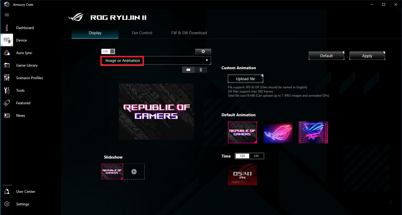
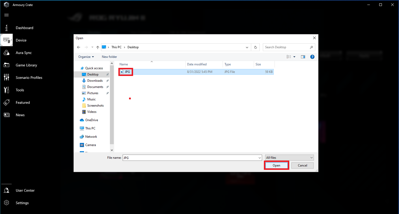
3.1.1 Custom animation: Click the [Upload file]

Select a pre-prepared picture or a GIF animation, as shown in the following picture in JPG format. Then click the [Open], as shown in the figure below:
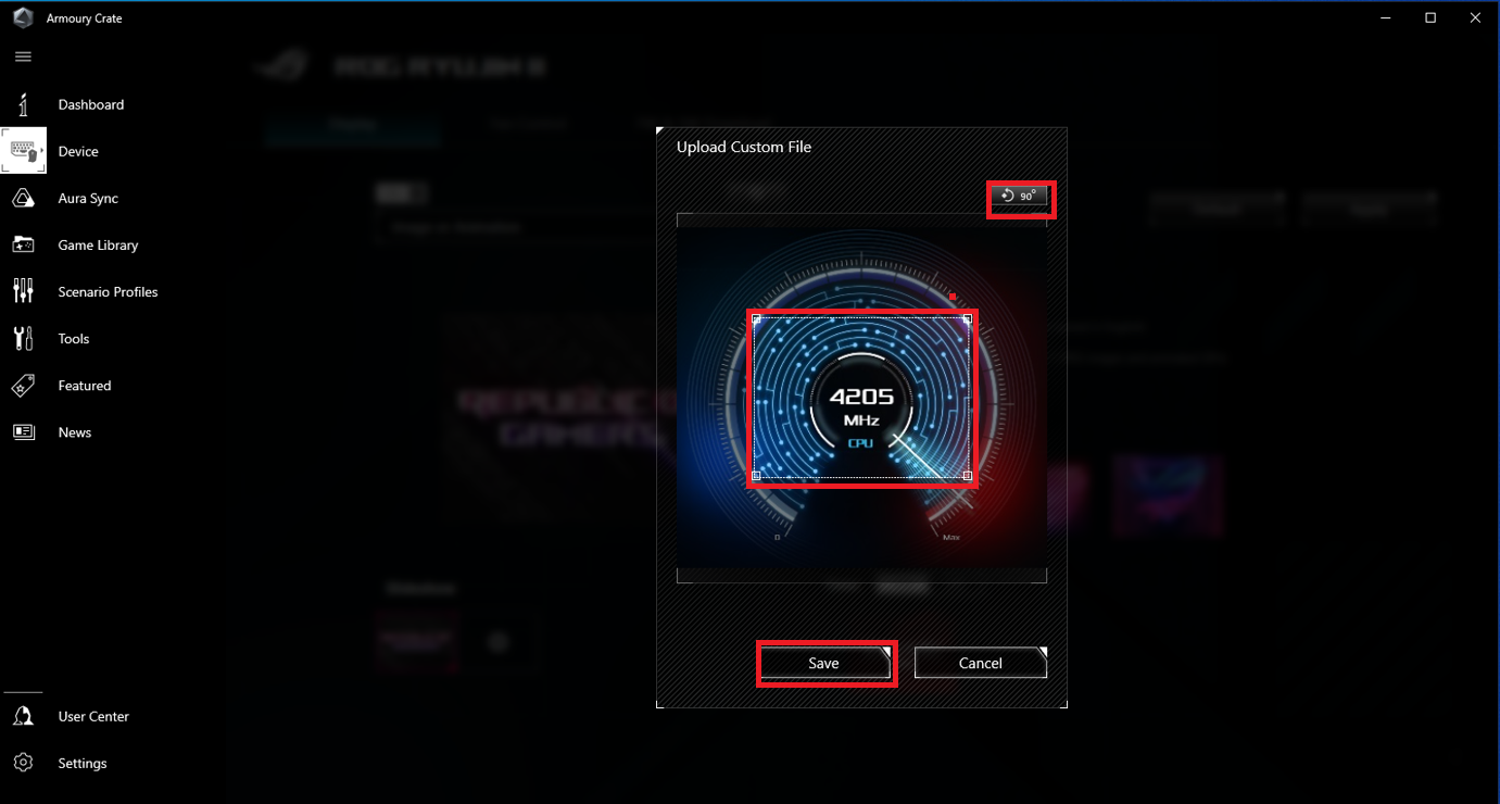
After uploading, you can re-adjust the size and angle of the image as shown in the figure below, click the [Save]
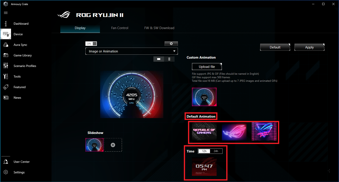
3.1.2 You can also choose [Default Animation], as shown in the figure below:
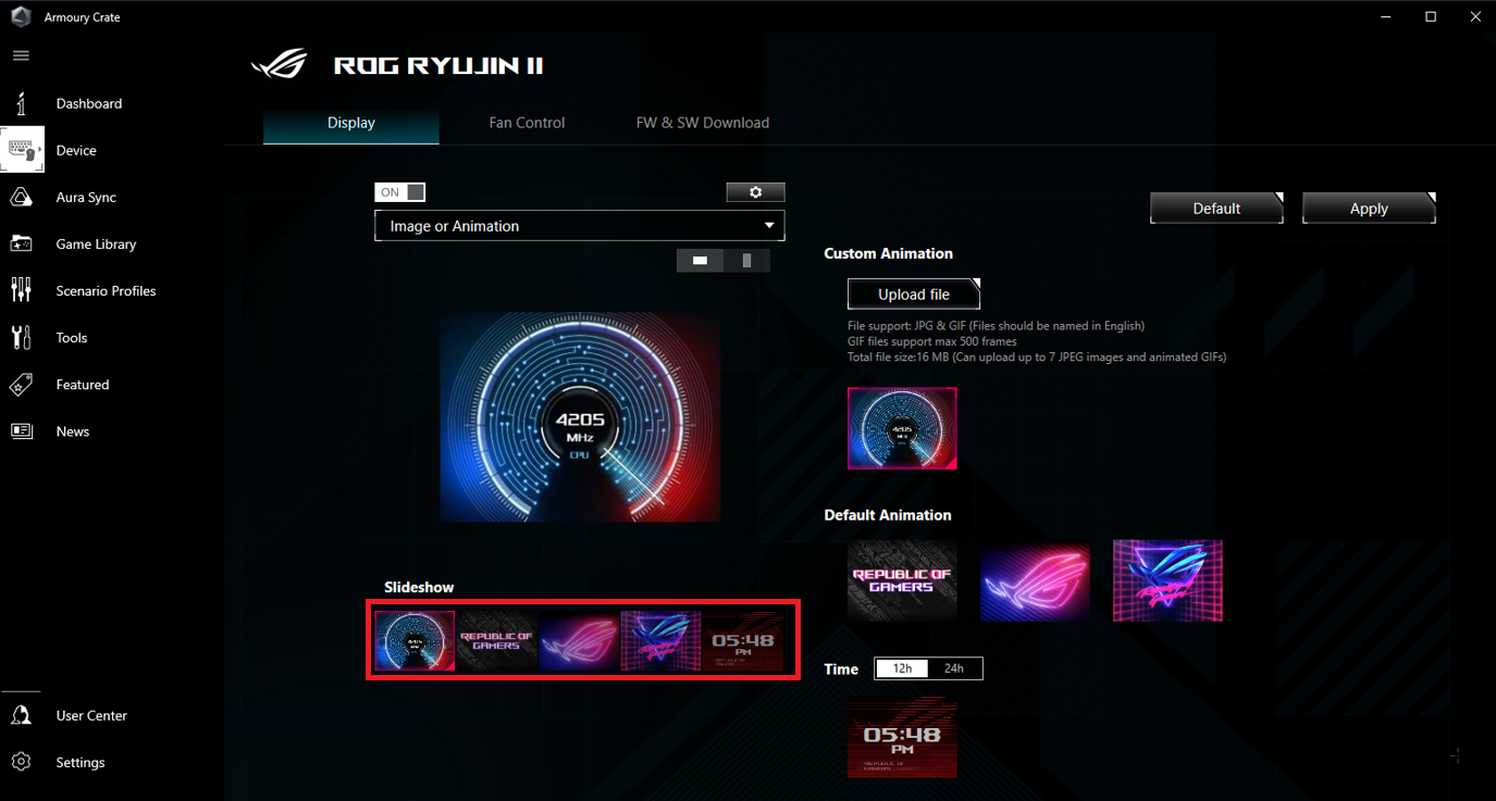
3.1.3 Slideshow: Add the displayed screen by clicking the [+] in Slideshow ,as shown in the figure below:
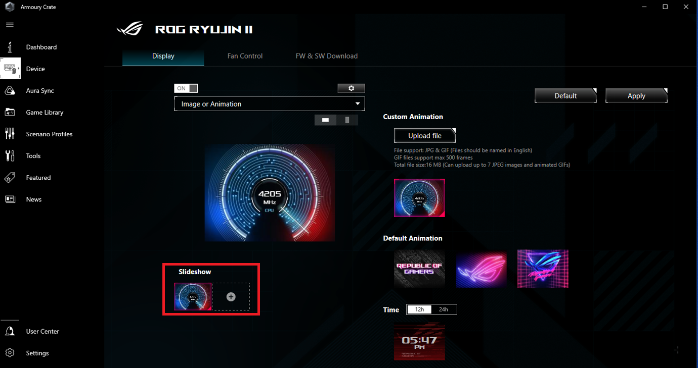
Up to 5 groups of pictures can be added
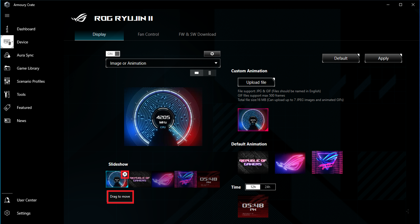
You can delete the picture by clicking the [X] in Slideshow, or you can click the [Drag to move] to exchange the location of pictures, as shown in the following figure:
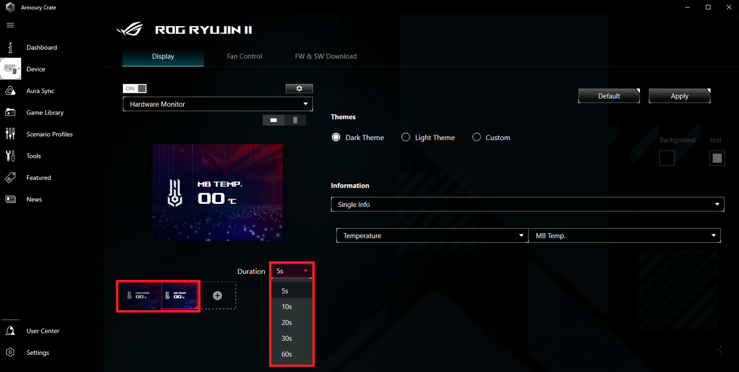
3.2 Hardware Monitor
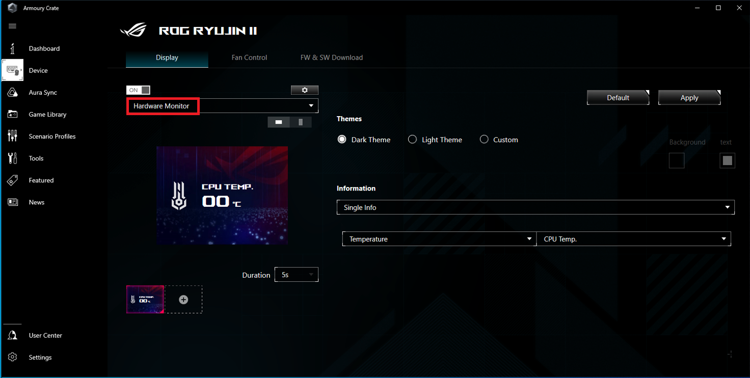
3.2.1 Themes: Dark Theme, Light Theme, Custom (customizable background and color of the text)
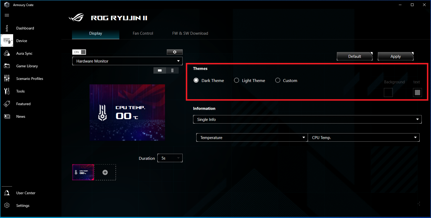
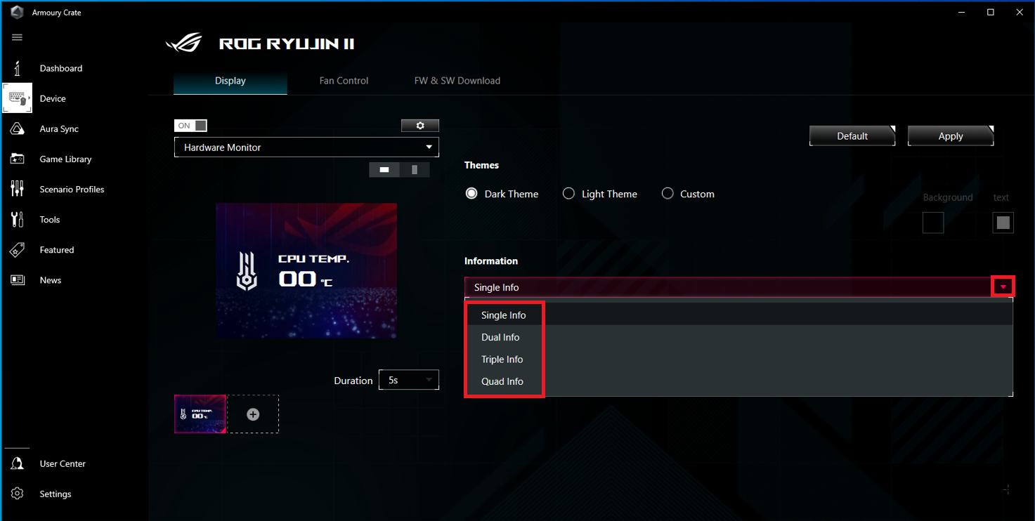
3.2.2 Information: Click the drop-down box to select the number of information to be displayed, the default is Single Info
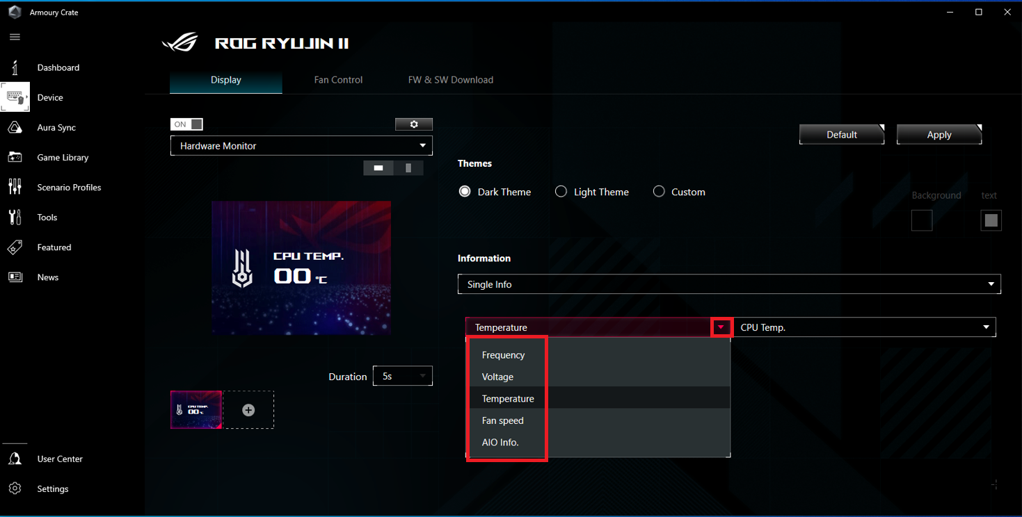
Click the displayed item, the default is Temperature, as shown in the following figure:
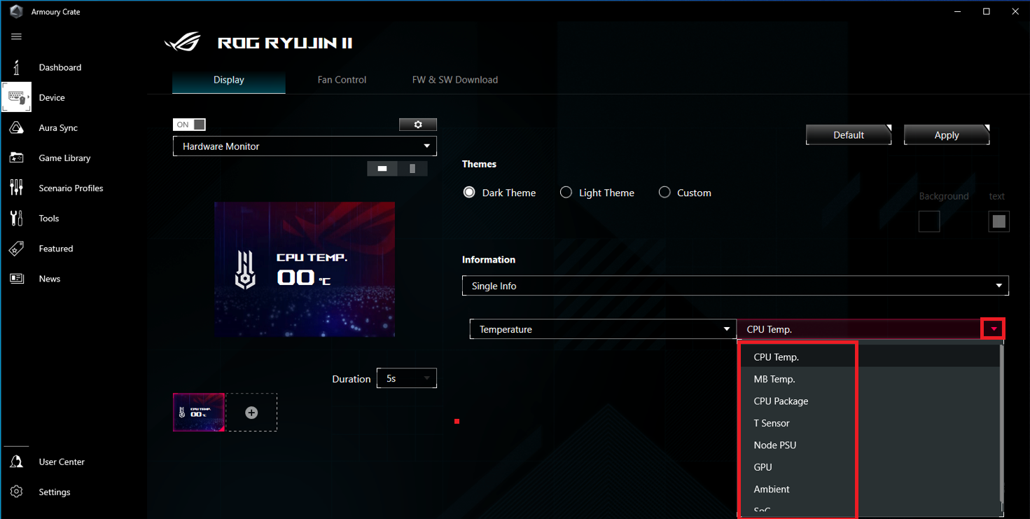
Click to select the item to be displayed, the default is CPU Temp , as shown in the following figure:
3.2.3 Duration: The default duration is 5S, when more than one screen is displayed, you can pull down to set the duration of each screen, the maximum is 60S
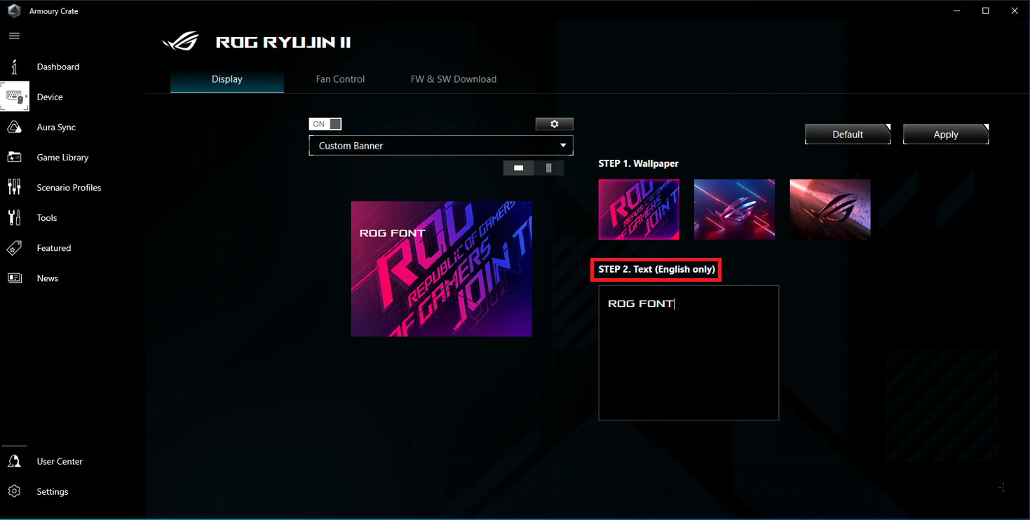
3.3 Mode three:Custom Banner
3.3.1 Wallpaper (preset templates can be selected)
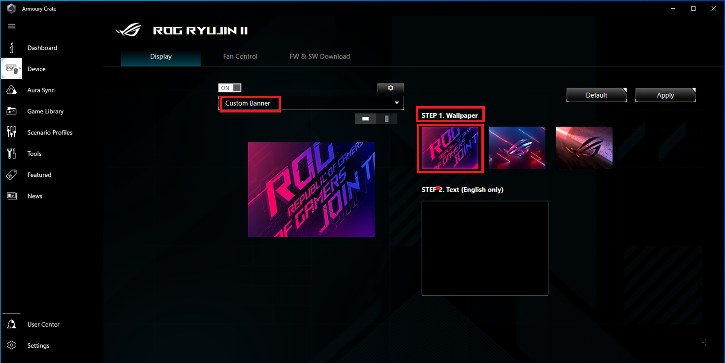
3.3.2 Text (you can enter the text you want to display on the LCD screen, only English capital letters are supported), click the [Apply] after the setting is completed
Method two:Set the LCD display of ROG RYUJIN II by AIDA64
1. Open the AIDA64
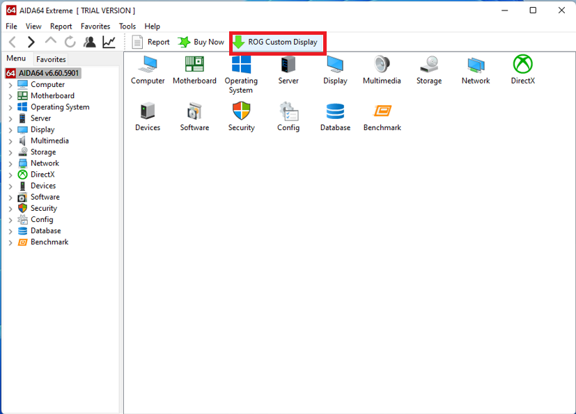
2. Click the [ROG Custom Display]
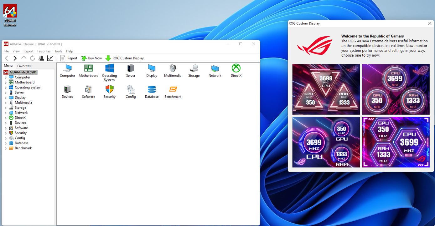
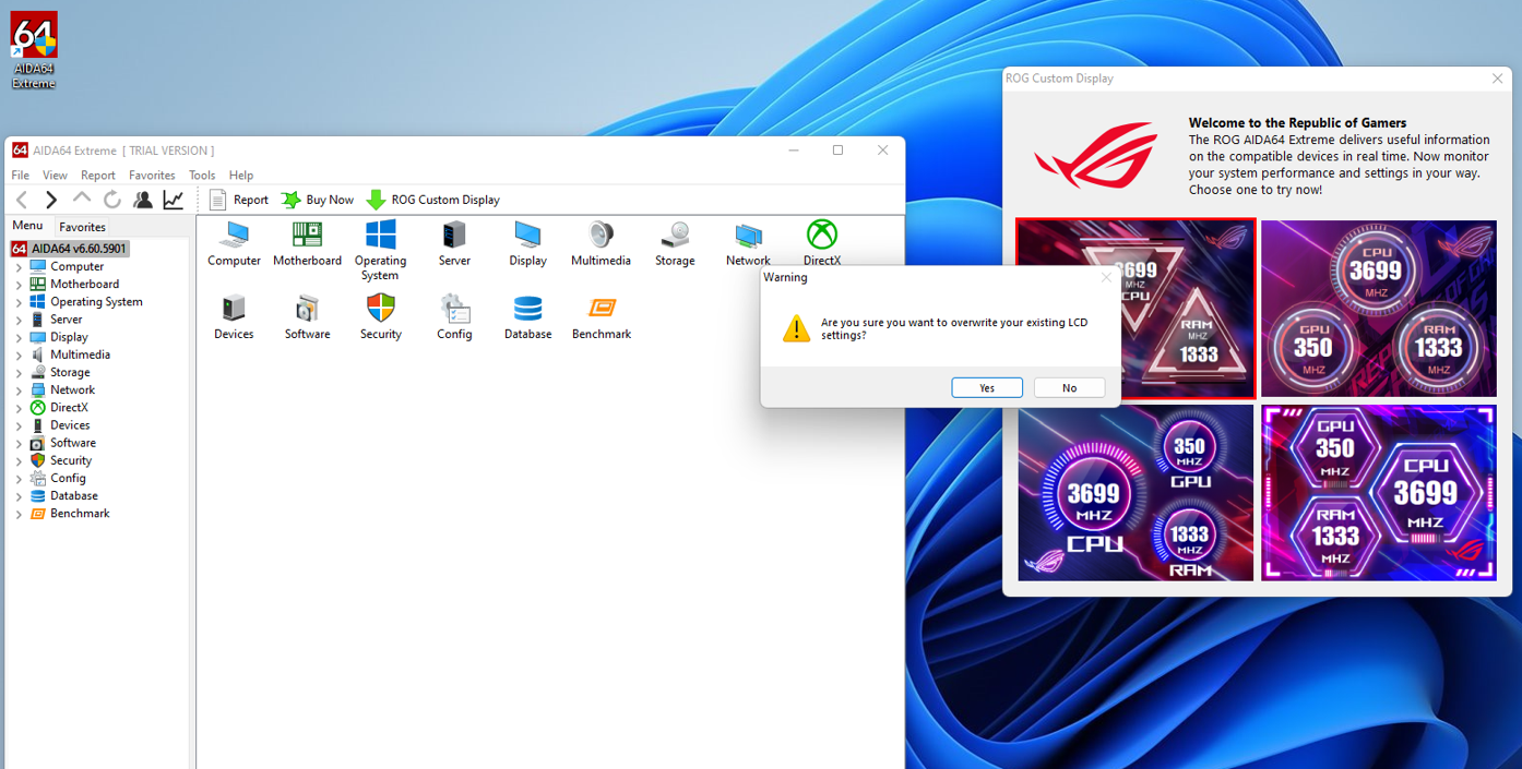
3. There are 4 different graphic interface display modes that can display the CPU/GPU/RAM frequency at the same time, you can select one of them and click the [Yes] in the prompt box, as shown in the figure below:
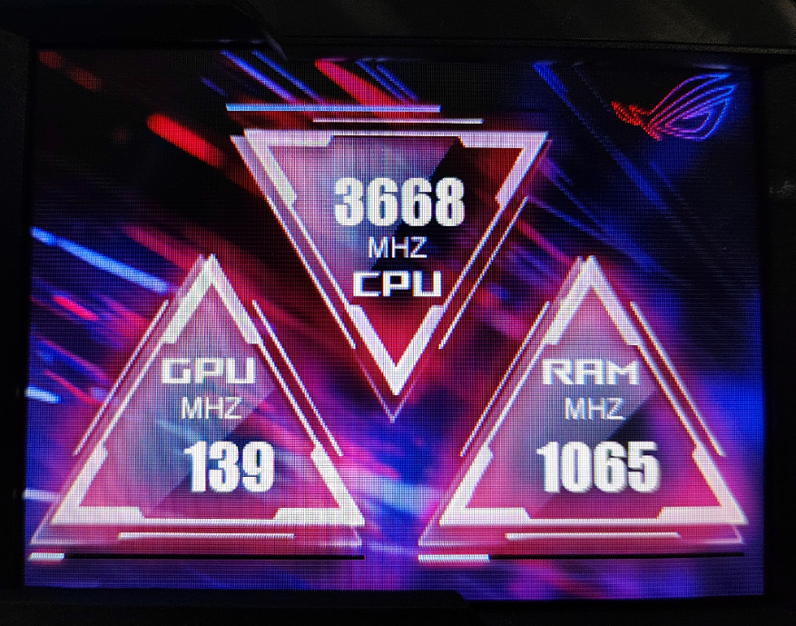
The following example selects the first graphical interface mode, and the actual display results are as following:
Q&A:
Q1: If you install Armoury Crate and AIDA64 software at the same time, how to set LCD display?
A1: When Armoury Crate and AIDA64 software are installed at the same time and the LCD display is set, the LCD will display the graphics mode set by Armoury Crate
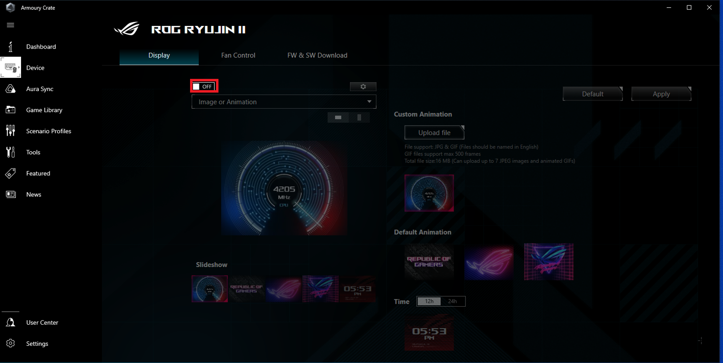
Q2: If you install Armoury Crate and AIDA64 software at the same time, and want to control LCD display by AIDA64, how to set it?
A2: Please set the Armoury Crate display control mode to [OFF] state, as shown in the figure below: